first hack: battery-less magic trackpad
This hack is something I’ve been meaning to do for a while, but only realized today I had all of the parts. The problem is I really like my magic trackpad, but I hate wasting batteries on it. It’s forever tethered to my desk, about six inches from all the power you could want coming out of USB ports. There are a couple problems. First, the trackpad has no input for power other than batteries. Also, The USB ports output 5v, and we need ~3v.
So, what’s a hacker to do? Build an adapter, of course. To do that, we’re going to need some supplies and tools.
-
A linear voltage regulator: https://www.adafruit.com/products/2165. This is one I had on hand. It turns 4-16v to a clean 3.3v, close enough for our purposes.
-
Perf board: https://www.adafruit.com/products/1609 . I like these because they have a power rail running down both sides.
-
Connectors. I used some male to female jumper wires I had in the junk drawer. That said, you could cut one of these in half: https://www.adafruit.com/products/1131 and use it for a more compact fit, if you don’t have stuff lying around.
-
Heat shrink tubing or electrical tape. Heat shrink is a lot neater: https://www.adafruit.com/products/344
-
USB cable.
-
Soldering iron, solder. If you’ve never soldered before, this isn’t the project to start on. We’re making structural joints as well as electrical.
-
Drill and bit: I think I used a 3/16th inch, use your judgement; it’ll need to be big enough to fit your connector through.
-
Board cutting implement: I used a pair of tin snips, but a Dremel would work as well, they’re just louder.
Now that you have all of your supplies, assembly is pretty easy.
-
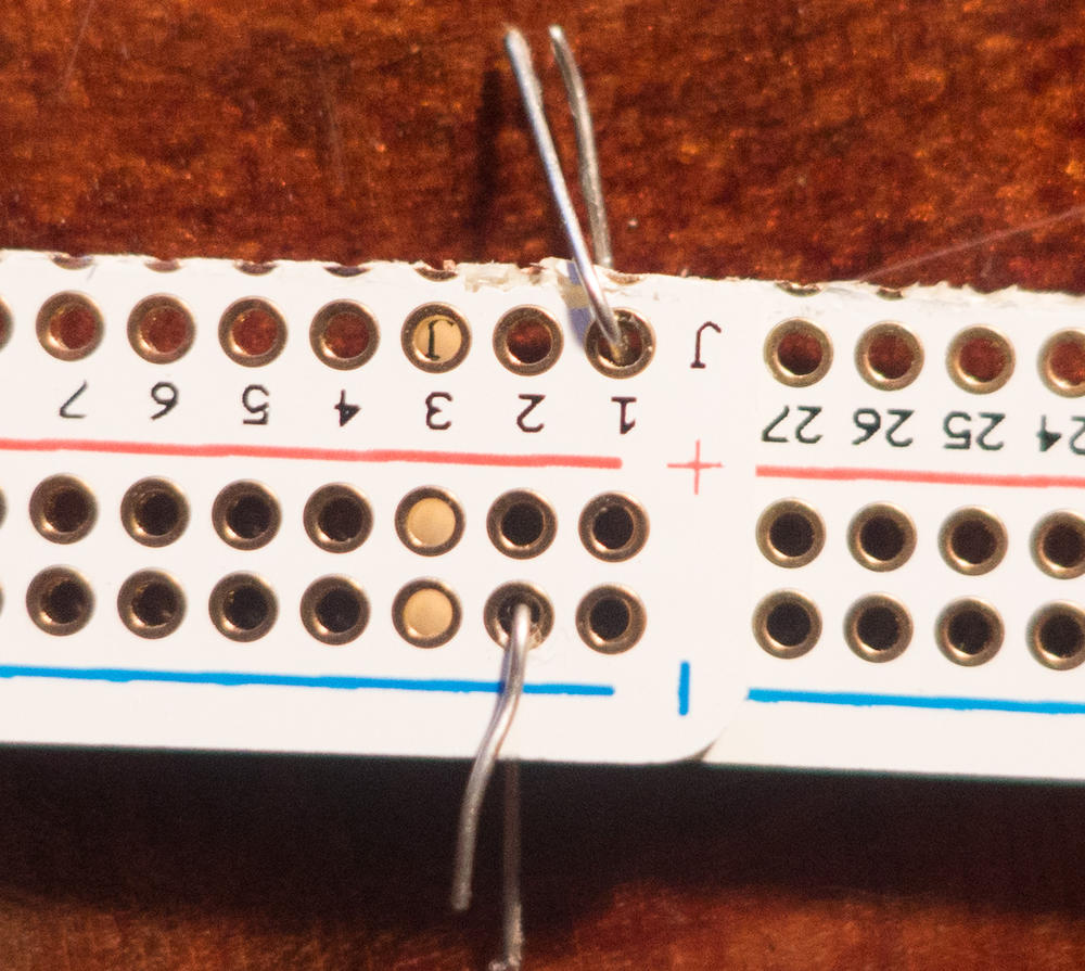
Cut the power strips off of the perma proto, leaving one row of extra holes on each side (as pictured).
-
Overlap two rows, so that you have six holes lined up in both boards. Above, I’ve used a couple bits of wire to hold them in place. Then, fill all of the overlapping holes with solder.
-
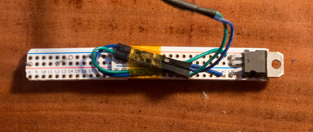
Now that the boards are attached, you can solder the regulator. The middle pin is Vcc, and looking at the top of the regulator (with the part numbers), Vin is on the right (bottom, in the picture of the completed adapter), and Ground is on the left (top, in the picture). I put Vin in the non-bus holes, because it only has to be connected to the usb. You want it to stick over the end a bit. The tab on top is also connected to Vcc, and will serve as the positive terminal.
-
Connect your connector to the board, in a way you can remember. For mine, green is ground. Then, cut and strip off the small end of the USB cable, and connect it to the other side of your connector. Red is Vin, and black will be ground. You can trim back the green and white wires, you won’t need them. If you have some heat shrink, remember to put it on before you splice. Solder and insulate the connections, in any case. This guide is a good one to look at to know if your splices are up to snuff.
-
If you have a multimeter, plug everything in and check; you should have about 3.3v between Vcc (Vout, on the datasheet for the regulator).
-
Trim the board to length. You need to be fairly accurate, but you can add a metal spacer if it’s too short.
-
Then, wrap a bare wire around the edge, so that it sticks out of the center. You want it to make contact with the end of the battery compartment. Connect this with ground. Check for shorts before you plug it in again; we don’t want to let the magic smoke out.
-
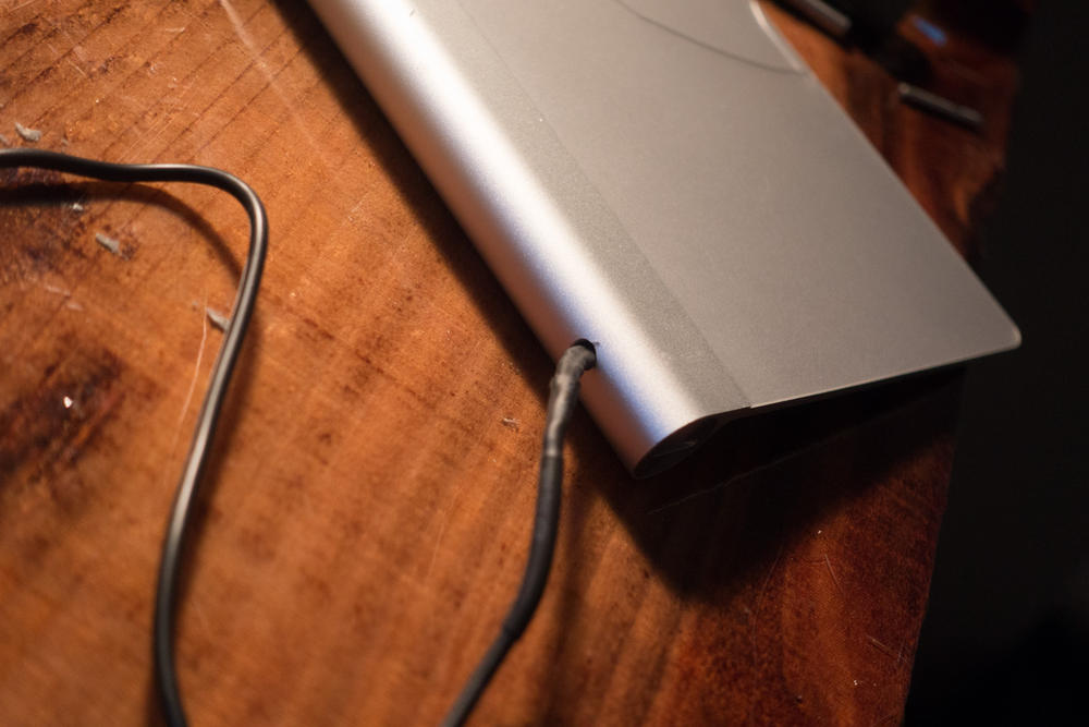
Remove any batteries that are in the trackpad (duh). Drill a hole in the on the back of the battery compartment. (see pictures) De-burr with a larger drill bit if you have one, but don’t fuss too much, it’s purely cosmetic.
-
Disconnect the USB cable and feed the connector through the hole. Hook it to the board connector, and then gently feed the whole assembly into the battery compartment. Screw in the cap, and connect the cable to power. You should be able to turn the trackpad on.


That’s it! It’s a lot of words for what was about 45 minutes of work. The sharp eyed reader may have noticed the jumper on mine; on the other side of the board, I’ve cut the traces, and moved ground over to the center, for a better position on the end connector.