wireless atreus with Adafruit Feather
This is a project that I’ve been pecking away at, a little at a time, for something like a year and a half. I knew it was possible, from the data sheets and example code. It just took me a long time to take the idea and make it into a reality. For context, I’m typing this on the finished board, and it works just as well as the stock Atreus.
The first step to making this was to rip out the micro from my wired atreus. If you’re starting this from scratch, you may be able to do it cheaper, since there’s not much to recommend a PCB build over a hand-wired build. I did the kit at first because I didn’t have time to put the effort into figuring out everything I needed to build this by hand, and by the time I decided to make it wireless, I already had all the parts on hand. That said, here’s our bill of materials:
- One Adafruit Feather 32u, with bluetooth
- One Perma-Proto or generic perfboard
- one Atreus kit OR the list of keyboard parts
- wire
- solder
Keyboard parts (only needed if you don’t already have an atreus):
- 42 cherry key switches, panel mount in your preferred tactility. I like the blues, myself.
- 42 signal diodes, such as these
- a mounting plate, which can be made by Ponoko or similar. Or 3d printed, if you have a big enough printer.
- more wire
The hand-wiring of a keyboard is beyond the scope of this post, and there are many good tutorials and videos of it.
With the materials in hand, all that’s left is a bit of creative soldering. The idea is to use the perf board as an adapter. So, first, I soldered in some header at the right places to mate with the atreus’ holes. Luckily everything is on 0.1” headers, we just have to deal with a little offset. There are three pins we can’t use on the Feather, they’re the ones marked SCK, MOSI, and MISO. They’re required for the bluetooth part of the operation.
You can see in the pictures how I’ve connected the feather to the header, and added some jumper wires to make everything work. It’s simple enough that I didn’t even bother doing a circuit diagram. A0-A5 line up with the shorter side, and the long side gets three jumper wires to pins 1, 2, and 3. If you’re hand wiring, you won’t need the adapter board, just solder each row and column to its own IO pin.
I had to cut a hole in the top of my atreus’ switch plate, in order to get to the solder holes, but if you’re assembling from scratch with the kit, you should do all this before you put the switches in, and then solder the adapter/feather assembly into the main PCB.
I also did a little modification to the feather: I switched out the JST connector for a micro-sized one that I had laying around. This allowed me to get away with slightly less height for the overall keyboard.
Then, I added a toggle switch to the ground line coming from the battery, hooked that and the positive terminal up to another connector, and plugged in the battery. I used some of the exposed pads to anchor the last connector; the mechanical connections are not electrically connected, so it works out. I could have made my life slightly simpler by soldering wires directly to the board, but I hadn’t worked out the entire strategy in advance; originally, I was going to just connect the battery to the micro-connector.
Once all that is done, and you have key the switches in, the firmware I’m using is here. It depends on the host OS for debounce; I haven’t had any issues yet on macOS, but YMMV, naturally. It’s otherwise kind of sloppy and in need of cleanup, but it works. The other thing is that there’s currently no third layer. Adding one would be pretty simple, but in practice I don’t need more than 84 keys (my ideal might be an atreus 64, actually).
This project is sort of a starting point from which I’d like to do a couple more keyboards. There’s this, and there’s the wireless ergodox build I’ve had on the back burner for quite a while, and maybe an atreus64 now that I know they exist.
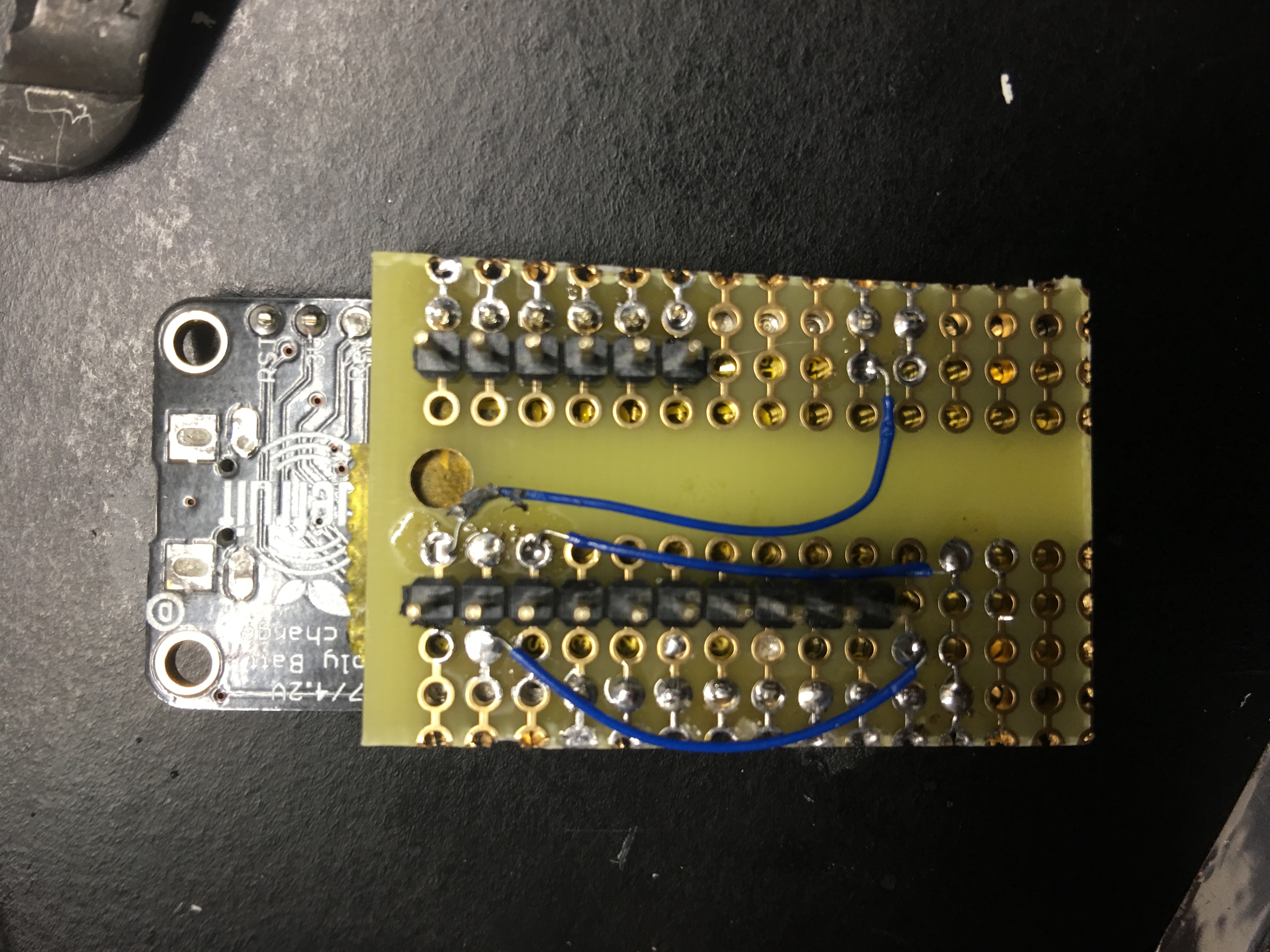 Illustration of my wiring. 30ga wire wrap wire to the rescue.
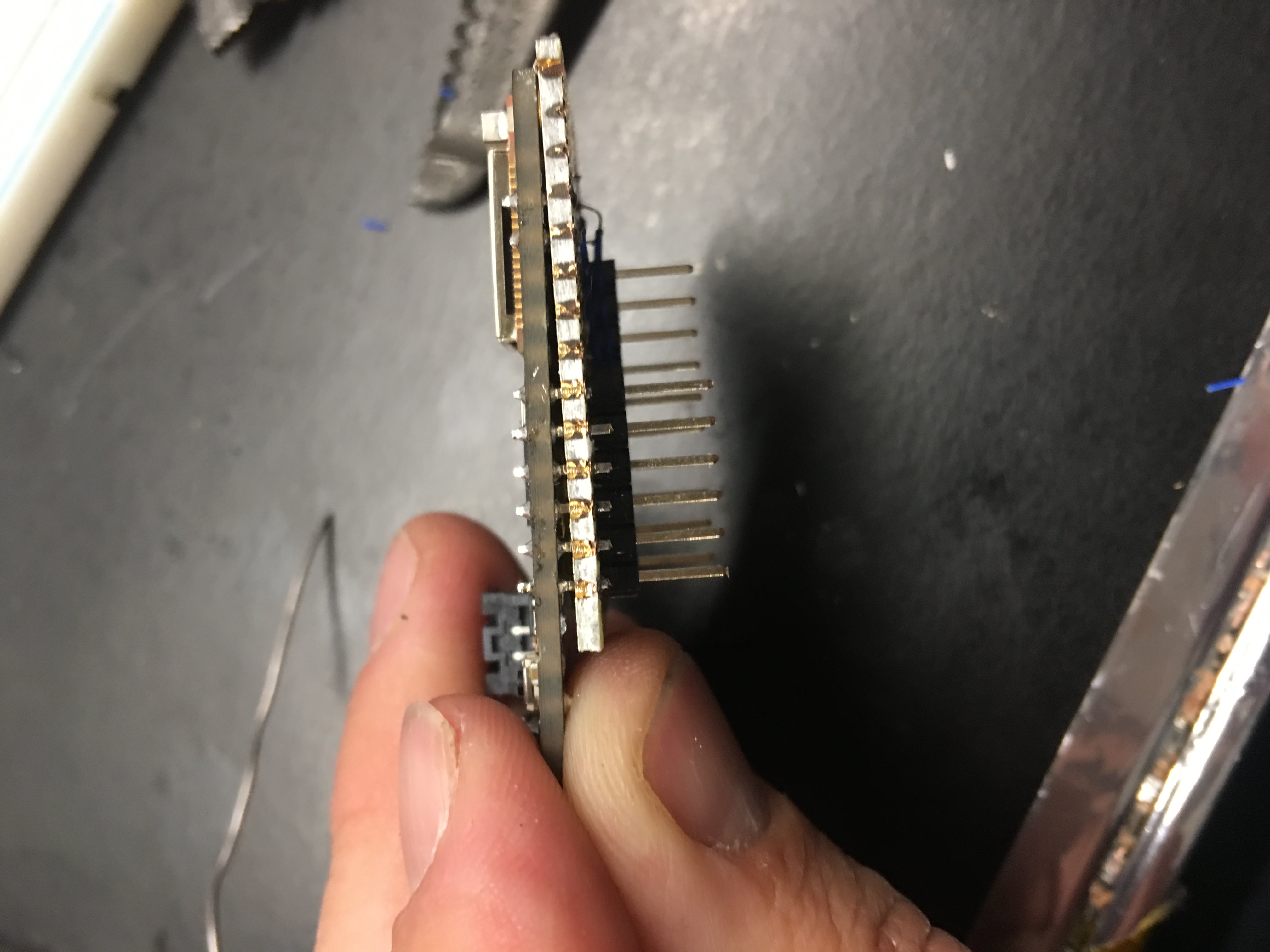 Side view of the adapter with the feather. Overall the assembly adds about 1/4” to the keyboard’s height.
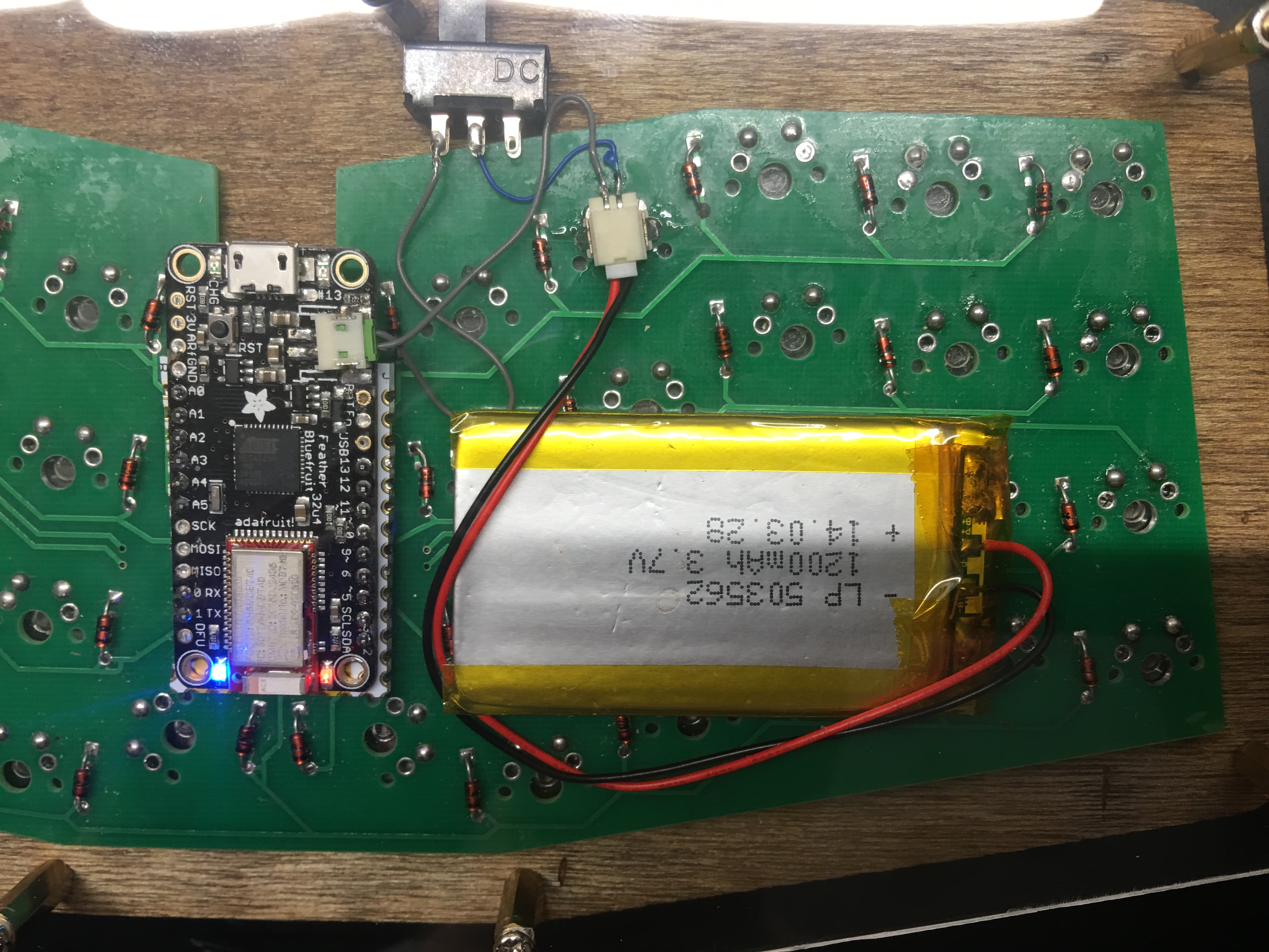 Close up of the completed assembly. You can see the switch, which is just glued to the switch plate, and the various connectors.
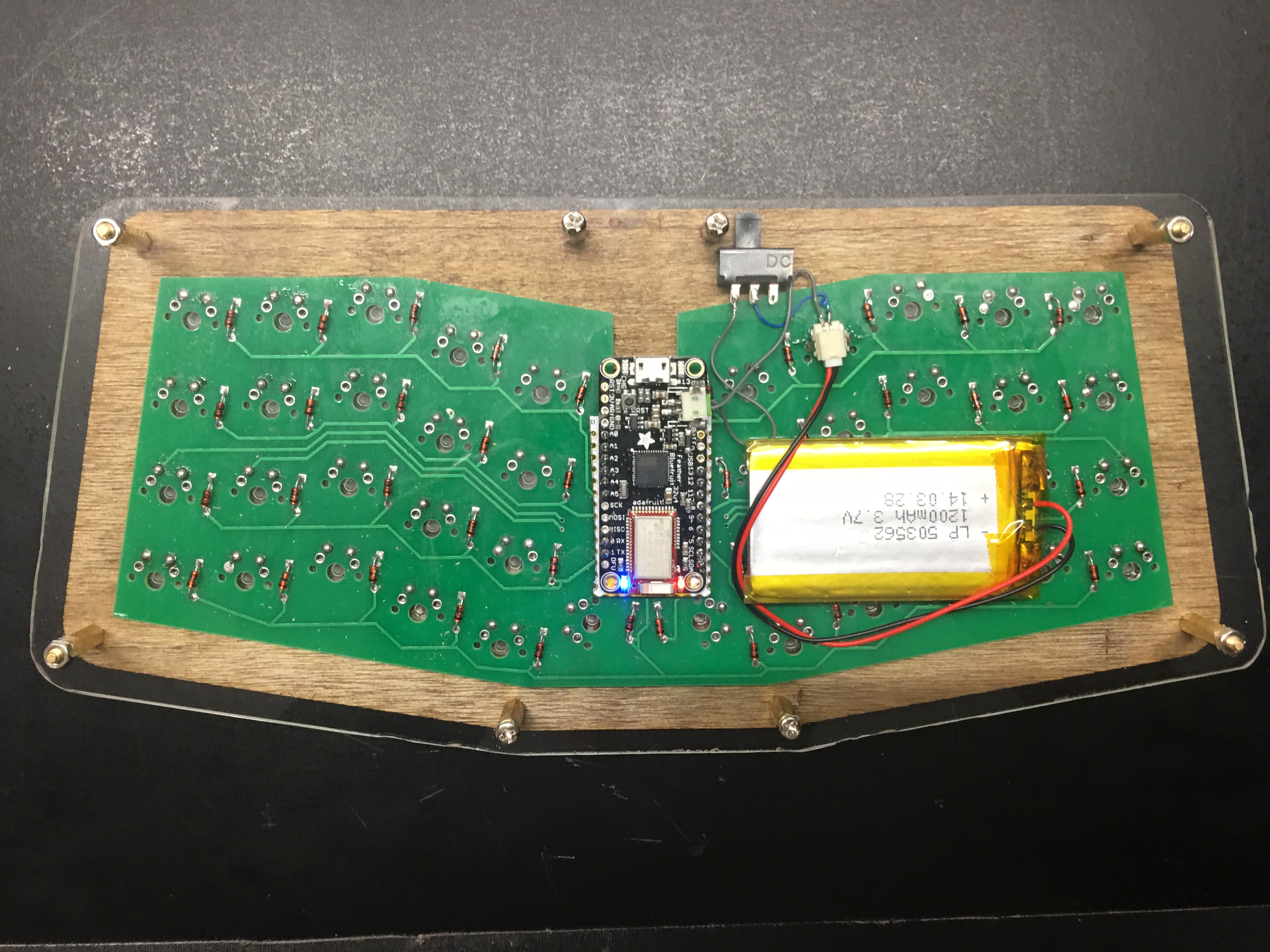 Wider view of the completed board. I’m using some M3 standoffs to give me the required height.
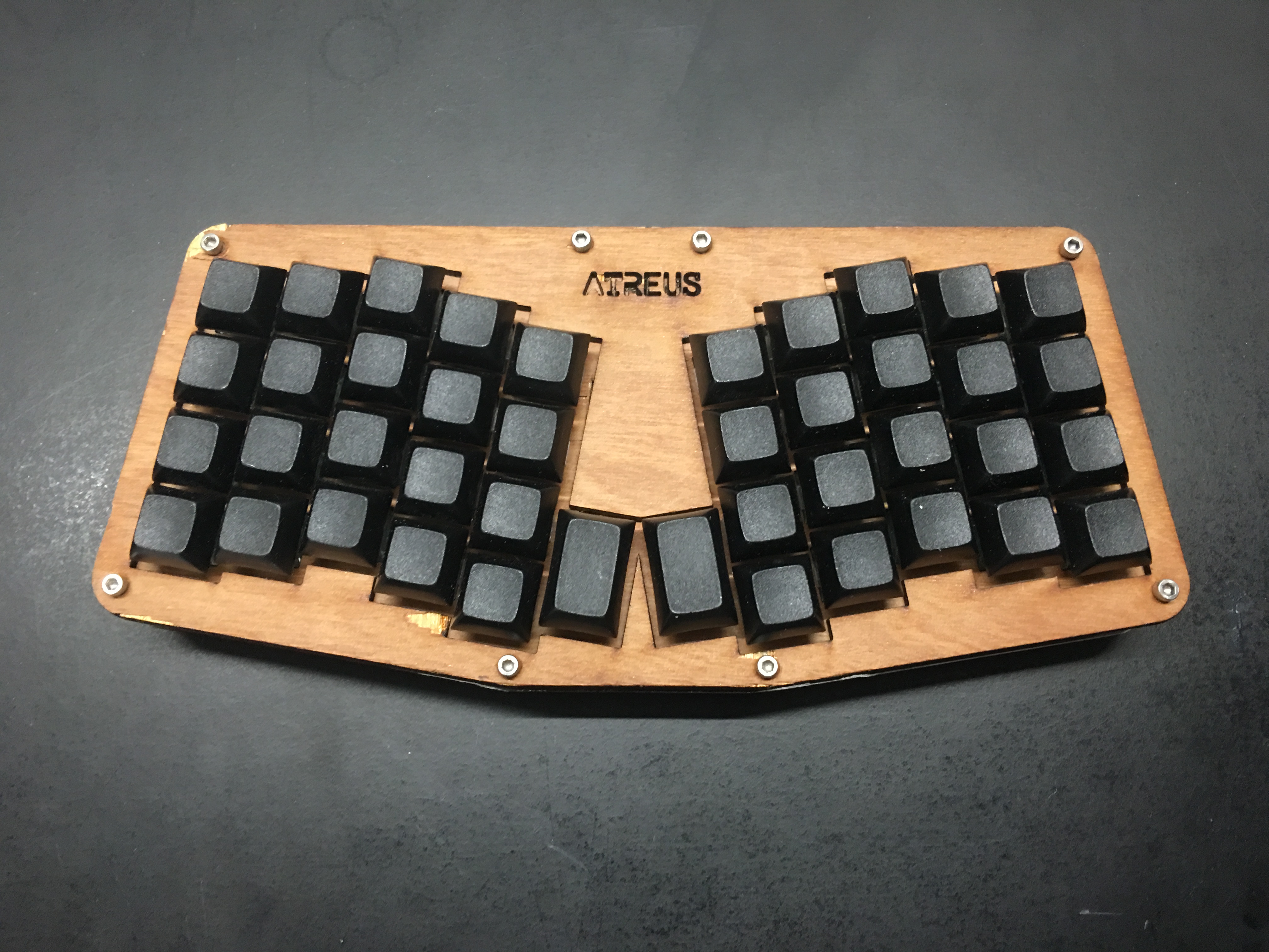 The top of the completed keyboard. It’s somewhat battered, and I may do another when I get my laser cutter up and running (parts inbound), but that’s yet another post.